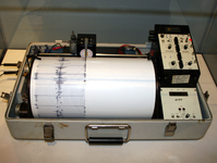


Seismometers are instruments that measure motions of the ground, including those of seismic waves generated by earthquakes, volcanic eruptions, and other seismic sources. Records of seismic waves allow seismologists to map the interior of the Earth, and locate and measure the size of these different sources.
Seismographs are equipped with electromagnetic sensors that translate ground motions into electrical changes, which are processed and recorded by the instruments’ analog or digital circuits. A record produced by a seismograph on a display screen or paper printout is called a seismogram. Although originally designed to locate natural earthquakes, seismographs have many other uses, such as petroleum exploration, investigation of the Earth’s crust and lower layers, and monitoring of volcanic activity.
A device involving water spillage was developed in 17th-century Italy. Later a water-filled bowl and still later a cup filled with mercury were used for detecting earthquakes and tremors. In 1855 Luigi Palmieri of Italy designed a seismometer, an instrument that senses the amount of ground motion. Palmieri’s seismometer consisted of several U-shaped tubes filled with mercury and oriented toward the different points of the compass. When the ground shook, the motion of the mercury made an electrical contact that stopped a clock and simultaneously started a recording drum on which the motion of a float on the surface of mercury was registered. This device thus indicated time of occurrence and the relative intensity and duration of the ground motion.
The basic problem in measuring ground motions is to attain a steady point that remains fixed when the ground moves. Various types of pendulums have been used for this purpose. The simplest type is a common pendulum in which a heavy mass is suspended by a wire or rod from a fixed point (as in a clock). Other forms are the inverted pendulum, in which a heavy mass is fixed to the upper end of a vertical rod pointed at its lower end, and the horizontal pendulum, in which a rod with a mass on its end is suspended at two points so as to swing in a nearly horizontal plane instead of a vertical plane. In 1840 a seismometer based on the common pendulum was installed near Comrie in Perthshire, Scotland.
Seismograph developments occurred rapidly in 1880 when Sir James Alfred Ewing, Thomas Gray, and John Milne, British scientists working in Japan, began to study earthquakes. Following a severe earthquake that occurred at Yokohama near Tokyo in that year, they organized the Seismological Society of Japan. Under its auspices various devices, forerunners of today’s seismograph, were invented. Among the instruments constructed in this period was Milne’s famous horizontal pendulum seismograph. A boom, to which the mass (M) was attached, was suspended horizontally by a pivot (P) and a silk thread (T) fixed to a point above the pivot. A thin plate (C), in which a narrow slit was cut parallel to the boom, was attached to the end of the boom. A similar plate with a slit at right angles to the upper plate was fixed on the top of a box containing a recording drum (D). A ray of light from an oil lamp passed through both slits and formed a small spot of light on a sheet of light-sensitive graph paper (bromide paper) wrapped on the recording drum. Milne successfully used this seismograph to record several earthquakes in Japan; then, after returning to England, he established a small worldwide seismographic network using such instruments.
The horizontal pendulum seismograph was improved greatly after World War II. The Press-Ewing seismograph, developed in the United States for recording long-period waves, was widely used throughout the world. This device employed a Milne-type pendulum, but the pivot supporting the pendulum was replaced by an elastic wire to avoid friction.